Wednesday, February 08, 2006
Friday, September 30, 2005
Friday, September 02, 2005
Finally some Phong shading :)

This is the model I used for phong shading. Soon I will be using different models. It is a geosphere and backface culling is done. The green lines show the face normals and the red the avg normal. Note.. the normals are not culled and therefor those that are behind can also be seen!
However only the face normals are now used and therefor you can see the outlines of the triangles.. I will be using the average normals soon.
- The light source is the eye itself.
- The light color is (1, 1, 1).
- The diffuse material color is (0.6, 0.6, 0.6) which is gray.
- The specular material color is (1, 0, 0) which is red.
- The specular light color is (1, 1, 1)... same as the diffuse light color.
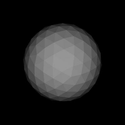
With no specular reflection and only diffuse component.

With shininess set to 1.

With shininess set to 10.
Note: Since only the face normals were used... the shading is not smooth and therefor the individual triangles are easily visible :)
Thursday, September 01, 2005
Refreshing memory... diffuse light (red book)
RGB Values for Lights and Materials
The color components specified for lights mean something different than for materials. For a light, the numbers correspond to a percentage of full intensity for each color. If the R, G, and B values for a light's color are all 1.0, the light is the brightest possible white. If the values are 0.5, the color is still white, but only at half intensity, so it appears gray. If R=G=1 and B=0 (full red and green with no blue), the light appears yellow.
For materials, the numbers correspond to the reflected proportions of those colors. So if R=1, G=0.5, and B=0 for a material, that material reflects all the incoming red light, half the incoming green, and none of the incoming blue light. In other words, if an OpenGL light has components (LR, LG, LB), and a material has corresponding components (MR, MG, MB), then, ignoring all other reflectivity effects, the light that arrives at the eye is given by (LR*MR, LG*MG, LB*MB).
Similarly, if you have two lights that send (R1, G1, B1) and (R2, G2, B2) to the eye, OpenGL adds the components, giving (R1+R2, G1+G2, B1+B2). If any of the sums are greater than 1 (corresponding to a color brighter than the equipment can display), the component is clamped to 1.
The ultimate diffuse light equation..
(max { L · n , 0} ) * diffuselight * diffusematerial
Where L = Normalised vector from vertex to light source.
n = Normal of the polygon at the vertex.
OR
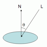

where I is the reflected intensity, Ld is the light's diffuse color (gl_LightSource[0].diffuse), and Md is the material's diffuse coefficient (gl_FrontMaterial.diffuse).
The color components specified for lights mean something different than for materials. For a light, the numbers correspond to a percentage of full intensity for each color. If the R, G, and B values for a light's color are all 1.0, the light is the brightest possible white. If the values are 0.5, the color is still white, but only at half intensity, so it appears gray. If R=G=1 and B=0 (full red and green with no blue), the light appears yellow.
For materials, the numbers correspond to the reflected proportions of those colors. So if R=1, G=0.5, and B=0 for a material, that material reflects all the incoming red light, half the incoming green, and none of the incoming blue light. In other words, if an OpenGL light has components (LR, LG, LB), and a material has corresponding components (MR, MG, MB), then, ignoring all other reflectivity effects, the light that arrives at the eye is given by (LR*MR, LG*MG, LB*MB).
Similarly, if you have two lights that send (R1, G1, B1) and (R2, G2, B2) to the eye, OpenGL adds the components, giving (R1+R2, G1+G2, B1+B2). If any of the sums are greater than 1 (corresponding to a color brighter than the equipment can display), the component is clamped to 1.
The ultimate diffuse light equation..
(max { L · n , 0} ) * diffuselight * diffusematerial
Where L = Normalised vector from vertex to light source.
n = Normal of the polygon at the vertex.
OR


where I is the reflected intensity, Ld is the light's diffuse color (gl_LightSource[0].diffuse), and Md is the material's diffuse coefficient (gl_FrontMaterial.diffuse).
DOT product... i keep forgetting it :(
Vector1 (x1, y1, z1) and Vector2 (x2, y2, z2).
DotProduct = (x1*x2 + y1*y2 + z1*z2)
The value is the cosine of the angle between the two input vectors, multiplied by the lengths of those vectors.
So, you can easily calculate the cosine of the angle by either, making sure that your two vectors are both of length 1, or dividing the dot product by the lengths.
Cos(theta) = DotProduct(v1,v2) / (length(v1) * length(v2))
Backface culling
When deciding if a polygon is facing the camera, you need only calculate the dot product of the normal vector of that polygon, with a vector from the camera to one of the polygon's vertices. If the dot product is less than zero, the polygon is facing the camera. If the value is greater than zero, it is facing away from the camera.
DotProduct = (x1*x2 + y1*y2 + z1*z2)
The value is the cosine of the angle between the two input vectors, multiplied by the lengths of those vectors.
So, you can easily calculate the cosine of the angle by either, making sure that your two vectors are both of length 1, or dividing the dot product by the lengths.
Cos(theta) = DotProduct(v1,v2) / (length(v1) * length(v2))
- Values range from 1 to -1.
- If the two input vectors are pointing in the same direction, then the return value will be 1.
- If the two input vectors are pointing in opposite directions, then the return value will be -1.
- If the two input vectors are at right angles, then the return value will be 0. So, in effect,
Backface culling
When deciding if a polygon is facing the camera, you need only calculate the dot product of the normal vector of that polygon, with a vector from the camera to one of the polygon's vertices. If the dot product is less than zero, the polygon is facing the camera. If the value is greater than zero, it is facing away from the camera.
Problems with normals... sucks
I was having lots of problems with normals. The back face culling was not working properly and the color was not distributed along the object properly. It took me one whole day to find out where the problem was...there was a small error in calculating the cross product of two vectors!! The y component of the normal was not correct. I had to render the normals of each face in order to find that the problem was with normals..Now its fixed and the pictures below show normals correctly :)

A geosphere showing average normals. I found a very easy way of calculating the average normals after the face normals have been calculated. The average normals are required when I want shade smooth object with phong shading... such as this geosphere will be rendered like a true sphere. If face normals (shown below) are taken then the edges of the polygon will be visible and it will not be a perfect sphere!! However average normals are not always desirable... for example a box should be rendered with the face normals instead of the average normals. Applying phong shading with avg normals will make the corners of the box look curved instead of being pointed... and therefor the shading would make the box look like a sphere (something else).

The face normals of each triagle drawn from the vertex.

A geosphere showing average normals. I found a very easy way of calculating the average normals after the face normals have been calculated. The average normals are required when I want shade smooth object with phong shading... such as this geosphere will be rendered like a true sphere. If face normals (shown below) are taken then the edges of the polygon will be visible and it will not be a perfect sphere!! However average normals are not always desirable... for example a box should be rendered with the face normals instead of the average normals. Applying phong shading with avg normals will make the corners of the box look curved instead of being pointed... and therefor the shading would make the box look like a sphere (something else).

The face normals of each triagle drawn from the vertex.
Sunday, August 28, 2005
Scanline and flat shading

Finally some scanlinen conversion with flat shading..The light direction is down the positive z-axis (0, 0, 1). Thanks to Wang I now know a bit more about the mathematics of perspective projection. The scene consists of a icosahedron and a box both of which have back face culled which means that only the front face are rendered. The z-buffer for hidden surface removal is also present but is not required here since backface culling is done.... but it will be required when object are rendered one infront of the other (the box infront of the icosahedron)
The matrix for perpective calculation...
float nearP = -1.0;
Matrix4 p( nearP, 0, 0, 0,
0, nearP, 0, 0,
0, 0, 1, 0,
0, 0, -1, 15 );
transformVertices(p);
normalizeTransformedVertices();
Friday, August 26, 2005
Phong Shading.... from the net
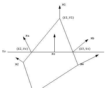
Phong Shading overcomes some of the disadvantages of Gouraud Shading and specular reflection can be successfully incorporated in the scheme. The first stage in the process is the same as for the Gouraud Shading - for any polygon we evaluate the vertex normals. For each scan line in the polygon we evaluate by linear intrepolation the normal vectors at the end of each line. These two vectors Na and Nb are then used to interpolate Ns. we thus derive a normal vector for each point or pixel on the polygon that is an approximation to the real normal on the curved surface approximated by the polygon. Ns , the interpolated normal vector, is then used in the intensity calculation. The vector interpolation tends to restore the curvature of the original surface that has been approximated by a polygon mesh. We have :


Source
Wednesday, August 24, 2005

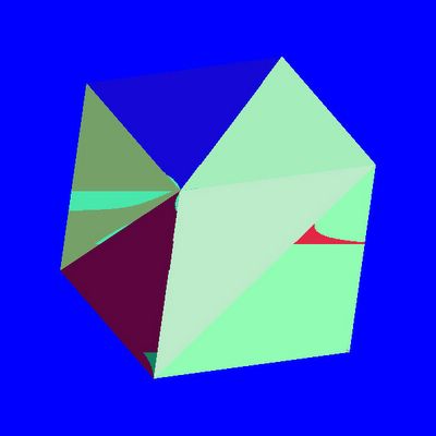
Hidden surface removal using software z-buffer (depth buffer)... It is not exactly working perfectly.. as you can see there are some holes made.. not sure why. Maybe because i am using floating point to store the depth values. I am going to try with double. If the problem exists then something is wronge with my algo (logical error!!). Hope i can fix this today and then i can concentrate on phong model.
:) There is now no lines that was present previously... i fixed it.
The box looks like they are rendered inside out. Thats because there is no perspective projection.


